
 English
 Español
 русский
 Français
Before a part ever reaches production, every buyer eventually asks the same question: should this component be injectio...
READ MORE
Content
A 180 g aluminum housing with 1.8 mm walls and a ±0.10 mm bearing bore is quoted in the same week as a 12 g stainless steel sensor body with a 0.4 mm wall. Both drawings land on the same buyer's desk, both are described as "high-volume", and both will be produced in a steel tool. They still belong in two different processes: the housing is a high-pressure die casting job, and the sensor body is a metal injection molding job. That is the short version of the die casting vs metal injection molding decision, and it almost never comes down to which process is technically superior.
The comparison is confusing because the two routes share vocabulary. Both inject material into a cavity, both are sold as net-shape processes, and both carry tooling amortization that forces a volume conversation. The similarities stop there. Die casting drives liquid metal into a die at tens of megapascals and freezes it in seconds, so the engineering problem is flow, thermal balance and porosity. Metal injection molding (MIM) injects a blend of fine metal powder and polymer binder, then spends a day or more removing the binder and sintering the powder into a solid, so the engineering problem is shrinkage, binder removal and furnace uniformity. One route leaves you with machining allowances; the other leaves you with a shrinkage factor.
What follows is a working comparison from the perspective of a shop that designs and builds aluminum die casting tooling and then runs production castings on it — including the numbers that usually decide a quotation, and the drawing changes that make one route look artificially expensive.
If the part is aluminum, larger than a matchbox, and needed in thousands per year, die casting is normally the cheaper and faster route. If the part is small, made of steel or a high-temperature alloy, and carries features that would otherwise be machined, MIM is often the only economic way to reach the drawing. Everything else is a variation on those two sentences.
The most common mistake is quoting both processes against the same unmodified drawing. A die casting design has draft, generous fillets, uniform walls and cored holes; a MIM design has fine ribs, sub-millimeter through-holes and near-net features with minimal draft. A part drawn for one process will look unnecessarily expensive in the other, and the comparison will be decided by a design decision rather than by process capability.
Die casting is a casting operation with a machine cycle measured in seconds. Molten alloy is ladled into a shot sleeve, a plunger drives it into the die cavity at high velocity, and the metal solidifies under intensification pressure inside a water-cooled steel die. The die opens, ejector pins release the casting, and the cycle repeats — typically 40 to 120 seconds for aluminum parts depending on wall thickness, die thermal balance and how many slides are working.
Cavity fill times for aluminum usually fall between 20 and 100 milliseconds. Intensification pressure sits around 50 to 100 MPa for most commercial housings and brackets. Die temperature is held near 180 to 250 °C so the alloy does not freeze before the cavity is full. Those three numbers explain the microstructure: rapid fill and rapid cooling produce a fine-grained, hard skin, while the slower-cooling interior is coarser and more prone to shrinkage porosity. Designers who understand this place thick sections where loads are low and keep ribs, bosses and bearing seats in the skin-dominated regions.
The die is more than a shape. Gate area sets fill velocity, overflow placement determines where oxides and cold shuts end up, and the thermal channels control the solidification sequence that decides where porosity forms. A die for a mid-size automotive housing typically delivers 100,000 to 150,000 shots before major refurbishment, so tool life belongs in the amortization calculation rather than in a footnote. Dies also carry the cost of slides and lifters: every undercut is a mechanism, and every mechanism adds maintenance to the production plan.
The workhorse family is Al-Si-Cu — A380 and its regional equivalents such as ADC12 — which casts well, machines acceptably and offers moderate strength. A360 trades some fluidity for better corrosion resistance and ductility. Magnesium AZ91D and AM60 are selected where weight matters more than elevated-temperature performance. Zinc alloys such as Zamak 3 and 5 are chosen for very thin walls, decorative surfaces and excellent dimensional stability. Conventional aluminum die castings cannot generally be solution-treated and aged to high strength without risking surface blistering from entrapped gas, which is why structural and safety-critical aluminum parts tend to use vacuum-assisted filling or pore-free variants of the process.
MIM borrows the shape-making logic of plastic injection molding and the densification logic of powder metallurgy. What leaves the mold is not yet a metal part — it is a "green" body held together by polymer, typically about 60% metal powder and 40% binder by volume.
Metal powder in the 5 to 20 micron range is compounded with a multi-component binder of waxes, thermoplastics and surfactants into pellets. That feedstock is injected into a steel mold at pressures far below die casting levels, and the tool is warm rather than thermally managed on a casting cycle. Walls down to 0.3 mm are achievable, and through-holes under 0.5 mm are routine. MIM molds are usually multi-cavity — 8 to 32 cavities is normal — and they last for hundreds of thousands of cycles because they see warm polymer-filled feedstock instead of molten metal at 650 °C.
The green part goes through debinding — solvent, thermal or catalytic — and then into a sintering furnace at 1,200 to 1,400 °C in hydrogen, vacuum or a controlled atmosphere. Powder particles bond by diffusion and the part densifies to roughly 95 to 99% of theoretical density. The furnace is the cost driver: a cycle runs 20 to 30 hours and is batched, so unit cost depends on how densely a load can be packed and how uniform shrinkage is across the load. That is also why MIM quotations are sensitive to annual volume in a way that die casting quotations are not — the machine that molds the part is rarely the constraint; the furnace is.
Linear shrinkage is typically 15 to 20% and is anisotropic in practice, driven by powder loading, binder system, gate location, part geometry and position in the furnace. This is why MIM tolerances are quoted as a percentage of the dimension rather than as a fixed band, and why thick sections are a problem: binder must escape from the interior, and a section much beyond 6 to 10 mm tends to debind unevenly, producing voids, cracks or distortion. Designers who treat MIM as "small die casting" usually discover this on the first thick boss.
The table below lists typical production ranges rather than best-case laboratory results. Use it to eliminate one route quickly, then validate the survivor with a real quotation and a design-for-manufacture review.
| Factor | High-pressure die casting | Metal injection molding |
|---|---|---|
| Typical alloys | Aluminum A380/ADC12, A360; magnesium AZ91D, AM60; zinc Zamak 3 and 5 | 316L, 17-4PH, 420, 4140, Inconel 718, Ti-6Al-4V, copper, tungsten heavy alloy |
| Part mass range | About 0.1 kg up to 10 kg and beyond; large housings and structural parts are common | Usually under 100 g; rarely above 200 g |
| Minimum wall section | 1.0-1.5 mm typical; 0.6-0.8 mm with thin-wall specialist capability | 0.3 mm achievable; sections above 6-10 mm become difficult |
| Linear tolerance | ±0.05-0.15 mm on small features, growing with part length | ±0.3% of dimension typical; ±0.1% with sizing or machining |
| As-produced surface | Ra 1.6-3.2 µm; tool marks and die texture transfer directly | Ra 1.0-3.0 µm as sintered; polishable to Ra 0.4 µm or better |
| Tooling cost | USD 30,000-250,000 depending on part size, slides and vacuum features | USD 8,000-40,000 for a multi-cavity mold |
| Cycle time | 40-120 s per shot, with multi-cavity or family tools possible | 10-40 s molding, plus 20-40 h of debinding and sintering |
| Economic volume | From roughly 1,000-3,000 pieces upward | From roughly 10,000 pieces upward; strongest above 50,000 |
| Density and porosity | Gas porosity possible; typically 1-3% by volume unless vacuum-assisted | 95-99% of theoretical density; fine and evenly distributed residual porosity |
| Draft and undercuts | 1-2° draft typical; undercuts require slides or lifters | Minimal draft; complex undercuts handled by tool splits |
| Secondary operations | Trimming, deburring, machining, impregnation, conversion coating, painting | Tumbling, sizing, machining of critical features, heat treatment, polishing |
Two rows deserve emphasis because they are misread most often. The tolerance row is a percentage versus a fixed band, which means MIM gets relatively better as parts get smaller and die casting gets relatively better as parts get larger. The porosity row is a metallurgical difference, not a quality grade: die casting porosity is a process artifact you design and inspect around, while MIM porosity is residual sintering porosity that behaves predictably under load.
Die casting tolerance behaves like a stack. The die is machined to tight limits, but thermal expansion, die wear, ejection distortion and shrinkage variation consume the budget during production. Published tolerance standards for precision aluminum die casting land near ±0.05 mm for the first 25 mm of a dimension, adding roughly ±0.02 mm for each additional 25 mm, with commercial grades looser. Anything tighter is a machining operation and should be quoted as one, ideally with the datum scheme agreed before the die is cut.
MIM tolerance is a percentage because shrinkage dominates the error budget. A ±0.3% production band is common, with ±0.1% achievable on selected dimensions after sizing or light machining. On a 10 mm feature, ±0.3% is ±0.03 mm, which is why MIM competes directly with machining on small precision components. On a 100 mm feature, the same percentage is ±0.3 mm and the advantage disappears.
Aluminum die casting prefers walls between 1.0 and 2.5 mm. Thinner walls demand higher fill velocity and better die thermal control; thicker walls cool slowly and produce internal shrinkage porosity, so a 6 mm solid boss is usually a design error. Ribs should be thinner than the adjoining wall — a common rule is 60 to 80% of wall thickness — with generous fillets to keep metal flowing and to spread ejection loads.
MIM handles thin walls and fine ribs well, but struggles with mass. Thick sections slow binder removal and create density gradients between the surface and the core. When a design needs a local thick section, the usual answer is a cored pocket or a redesign rather than a process change.
Die castings need draft because the part shrinks onto cores and grips the die. One to two degrees per side is normal; half a degree is possible with polished surfaces and well-controlled ejection, but it raises tool cost and scrap risk. Undercuts require slides, lifters or split cavities, each of which adds tooling cost, maintenance and cycle time. A design with four undercuts can double tooling cost relative to the same part with none.
MIM needs very little draft because the green part is slightly compressible and shrinks away from the cavity during sintering. Internal undercuts and cross-holes are frequently molded rather than drilled, which is the single biggest reason MIM wins on small complex hardware such as locking components, surgical instruments and orthodontic brackets.
Die casting has no practical upper limit until the machine tonnage runs out: 1,600 to 2,500 tonne machines routinely produce 5 to 10 kg aluminum housings, and larger cells exist. MIM has a real ceiling. Most production parts sit under 100 g, parts between 100 and 200 g are possible, and anything above that competes with investment casting and machining on cost and with the furnace on physics.
The material question usually ends the debate faster than the tolerance question. Die casting is a low-melting-point process; MIM is a sintering process that can reach steel, nickel and titanium families. Aluminum is technically possible in MIM but is rarely practical because of oxide formation and cost, so any aluminum part belongs in a casting route.
| Material family | Die casting | Metal injection molding | Typical application driver |
|---|---|---|---|
| Aluminum (A380, ADC12, A360) | Primary route | Not practical | Lightweight housings, heat dissipation, large parts |
| Magnesium (AZ91D, AM60) | Primary route | Rare | Weight-critical portable and automotive parts |
| Zinc (Zamak 3, 5) | Primary route | Rare | Thin walls, decorative hardware, dimensional stability |
| Stainless steel (316L, 17-4PH, 420) | Not viable | Primary route | Corrosion resistance, hardness, small precision parts |
| Low-alloy steel (4140, 4605) | Not viable | Primary route | Wear parts, gears, structural hardware |
| Titanium (Ti-6Al-4V) | Not viable | Established niche | Medical implants, aerospace brackets, low weight with strength |
| Copper and brass | Conditional | Available | Conductivity and wear resistance |
| Tungsten heavy alloy | Not viable | Primary route | Radiation shielding, balancing weights, high density |
A practical consequence: if the design review establishes that the alloy must be a stainless steel, die casting is not a candidate and the comparison becomes MIM versus machining versus investment casting. If the alloy must be aluminum and the part is over 200 g, MIM is not a candidate and the comparison becomes die casting versus gravity casting versus fabrication.
A die casting is not metallurgically uniform. The skin that froze against the die is dense and fine-grained; the interior cooled more slowly and carries gas and shrinkage porosity. Elongation and fatigue performance are therefore direction- and location-dependent, and a tensile test cut from a test bar will not represent a boss in the middle of a 5 mm section. High-integrity applications address this with vacuum-assisted filling, squeeze pins, careful overflow design, and acceptance criteria written around radiography or density checks rather than around a single tensile number.
A sintered MIM part is chemically and structurally uniform, with residual porosity of roughly 1 to 5% that is fine and evenly distributed rather than concentrated. Properties behave more like a wrought material, and heat treatment of alloys such as 17-4PH works predictably because there is no entrapped gas to blister. The trade-off is ductility and impact toughness: sintered parts with residual porosity are generally less forgiving than a fully dense wrought or forged part, and fatigue strength scales with density.
Aluminum die castings are usually used as-cast or given a stress relief; T6 treatment is limited by the blistering risk mentioned earlier. Zinc die castings are often used as-cast with decorative plating. MIM parts can be annealed, quenched and tempered, case hardened, or hot isostatically pressed to close residual porosity when the application justifies the cost — a route that has no equivalent in high-pressure die casting.
Die casting tooling is expensive because it is a hardened hot-work steel tool with thermal management, slides, a runner and overflow system, and often vacuum hardware. A modest single-cavity tool for a small bracket might start near USD 30,000; an automotive structural die with multiple slides, vacuum and a die-cast trim press can exceed USD 200,000. That investment is justified by cycle time and part size, not by precision.
MIM tooling is cheaper per cavity because the mold sees warm feedstock, not molten metal. A 16-cavity mold for a small component commonly lands between USD 15,000 and USD 40,000. The savings on tooling are then partly spent on the sintering furnace, fixtures, and the process development needed to hold shrinkage.
Die casting wins decisively on cycle time per part: a 60-second shot in a two-cavity die yields 120 parts per hour, and the part is finished when it leaves the trim press. MIM molding is fast in the same way — 20 seconds in a 16-cavity tool is thousands of green parts per shift — but the furnace cycle that follows runs 20 to 40 hours. Throughput therefore depends on furnace capacity and load density, which is why MIM suppliers talk about kilograms per load rather than shots per hour.
The break-even calculation is straightforward once tooling and unit cost are known. Total cost equals tooling plus unit price times quantity. Die casting typically has high tooling and low unit cost; MIM has lower tooling and a unit cost that falls with volume but never reaches die casting levels for a comparable mass of metal. As a working rule, aluminum die casting is competitive from roughly 1,000 to 3,000 pieces upward, while MIM becomes viable around 10,000 pieces and clearly advantageous above 50,000. Below those thresholds, machining, sand casting or a fabricated assembly usually wins — and a supplier who quotes production tooling at 500 pieces is signaling either a misunderstanding of your program or an intention to recover tooling cost in the piece price.
A die casting reproduces the die surface. A polished die cavity gives a glossy part; an EDM-textured cavity gives a matte or grained part. As-cast roughness of Ra 1.6 to 3.2 µm is normal, and cosmetic surfaces are achieved through die polishing plus a coating or paint system. Flashing at the parting line must be trimmed, and any machining allowance has to be designed in from the start — typically 0.3 to 0.8 mm on surfaces that will be cut.
A MIM part comes out of the furnace with a matte, slightly grainy surface at Ra 1.0 to 3.0 µm. It can be tumbled, shot-blasted, polished, plated, passivated or machined. Because the part is already near-net shape and often small, secondary machining is usually limited to a few critical features such as a bearing bore or a sealing face, and the decision to machine should be made at the design stage so the shrinkage allowance is correct.
For both processes, the cheapest secondary operation is the one designed out. Specifying a cosmetic Class A surface on a hidden bracket, or a ground finish on a feature that only needs Ra 3.2 µm, adds cost that no process choice can recover.
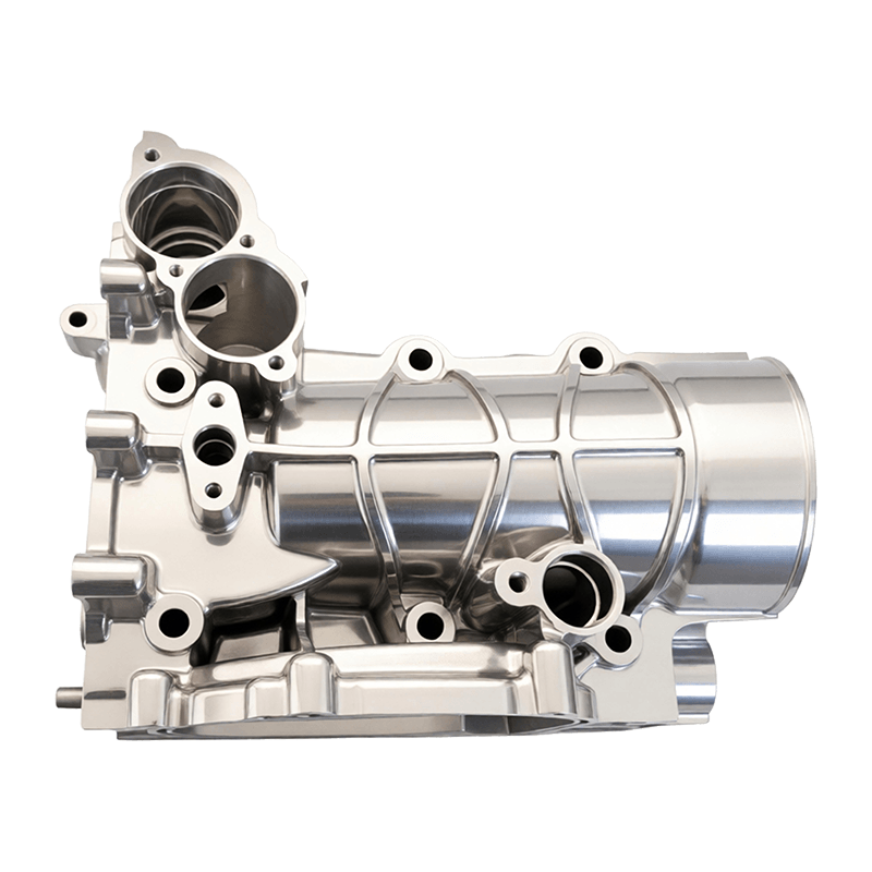
Aluminum die casting dominates wherever a part is structural, thermal or large. In vehicles, that means transmission and clutch housings, oil pans, controller and inverter housings, e-drive reducer housings, battery trays and body structural members such as longitudinal beams and shock towers. Outside automotive, it covers telecom filter and heat-sink cavities, photovoltaic inverter housings, energy storage plates, pump bodies, motor housings, robot joint structures and appliance components.
The shift toward electric drivetrains has increased demand for large, thin-walled, leak-tight aluminum housings, and vacuum-assisted die casting has become the standard answer. Designers working on these programs often find the practical constraints documented in supplier technical notes; our own review of how die casting is reshaping new energy vehicle parts covers the wall-thickness and leak-rate trade-offs in more detail.
 Die-Cast Aluminum Battery Tray for New Energy VehiclesA structural battery-system component in aluminum, positioned for the large, thin-walled housings discussed here; review for OEM/ODM die-casting programs.View Product →
Battery trays illustrate the point well: they are large, they carry stiffness and sealing requirements, they need integrated cooling channels or mounting bosses, and they are produced in the thousands rather than the millions. That combination sits squarely in die casting territory and outside MIM's size envelope.
MIM owns the small, dense, feature-rich end of the market: surgical instrument jaws and trocars, orthodontic brackets, implant components, firearm hammers and sears, watch cases and clasps, sensor housings, micro-gears, hinge components, locking hardware, and small structural brackets in consumer electronics. The common thread is a part small enough to mold in high cavitation, complex enough that machining would require multiple setups, and used in a material that die casting cannot melt.
A useful test: if the part could be produced by machining from bar stock in two operations, MIM will struggle to justify tooling. If it would need five operations, two fixtures and a deburring step, MIM usually wins on total cost even at moderate volumes.
Most process comparisons fail at the RFQ stage because the package is incomplete. Send the following and the quotation will be comparable:
For automotive work, an IATF 16949 certified quality system is a baseline rather than a differentiator. What matters more in practice is how the supplier controls the specific process: die thermal balance and shot monitoring for die casting, and powder lot traceability, debinding parameters and furnace logs for MIM. Ask to see the control plan for the characteristics you care about, not the certificate on the wall.
Piece price is a poor comparison metric on its own. Add tooling amortization over realistic volume, machining and coating costs, freight, inventory carrying cost from longer furnace or die lead times, and the cost of scrap and rework at the rates the process actually delivers. Die casting scrap is often in the low single digits once the die is stable but can spike during the first weeks of a new tool; MIM scrap is usually low after process qualification but can be significant during shrinkage tuning.
Because most die casting comparisons are decided by tooling design rather than by the machine, it helps to work with a supplier that controls both. Ningbo Dinghong Mould Co., Ltd. operates from the high-end mold park in Beilun, Ningbo, close to the port, and combines die casting mold design and manufacturing with aluminum die casting production, machining and trade — an arrangement that traces back to moldmaking experience dating from 1998 and a company established in 2013.
The practical value of that structure shows up in three places. First, gating and overflow design is done by the same team that will run the casting trials, with mold flow simulation used to check fill and solidification before steel is cut. Second, the mold and the part are quoted together, so the customer can see which portion of the price is tooling and which is conversion cost — useful when volumes are uncertain. Third, quality control has been organized around automotive expectations since ISO 9001 and IATF 16949 certification in 2017, with in-house inspection equipment supporting first-article and production audits.
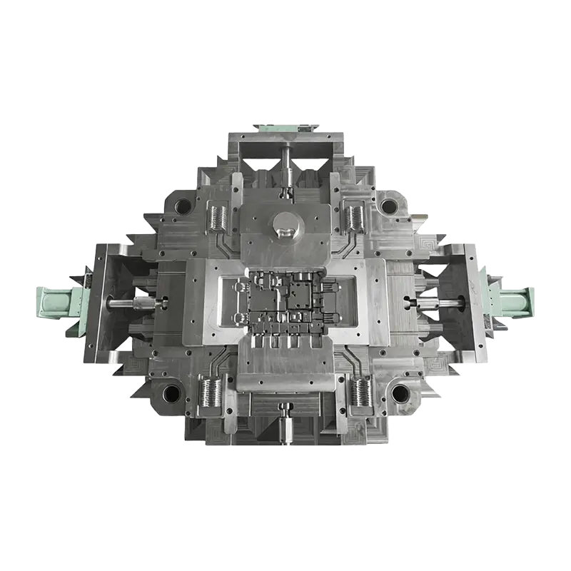
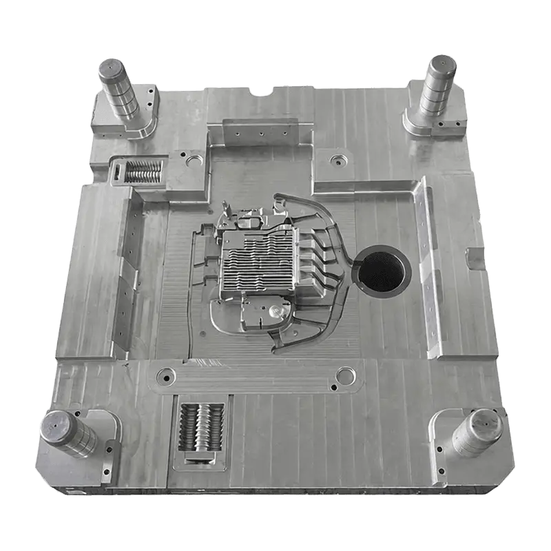
The product range reflects where aluminum die casting is actually consumed: powertrain and transmission housings, clutch and oil-pan components, e-drive reducer and controller housings, battery trays, motor and electronic control unit castings, body structural parts, plus telecom filter housings, inverter housings, pump bodies, robot components and appliance parts. A dedicated die casting molds line covers automotive controller and gear chamber tooling, and the same engineering team supports castings production once the tool is proven.
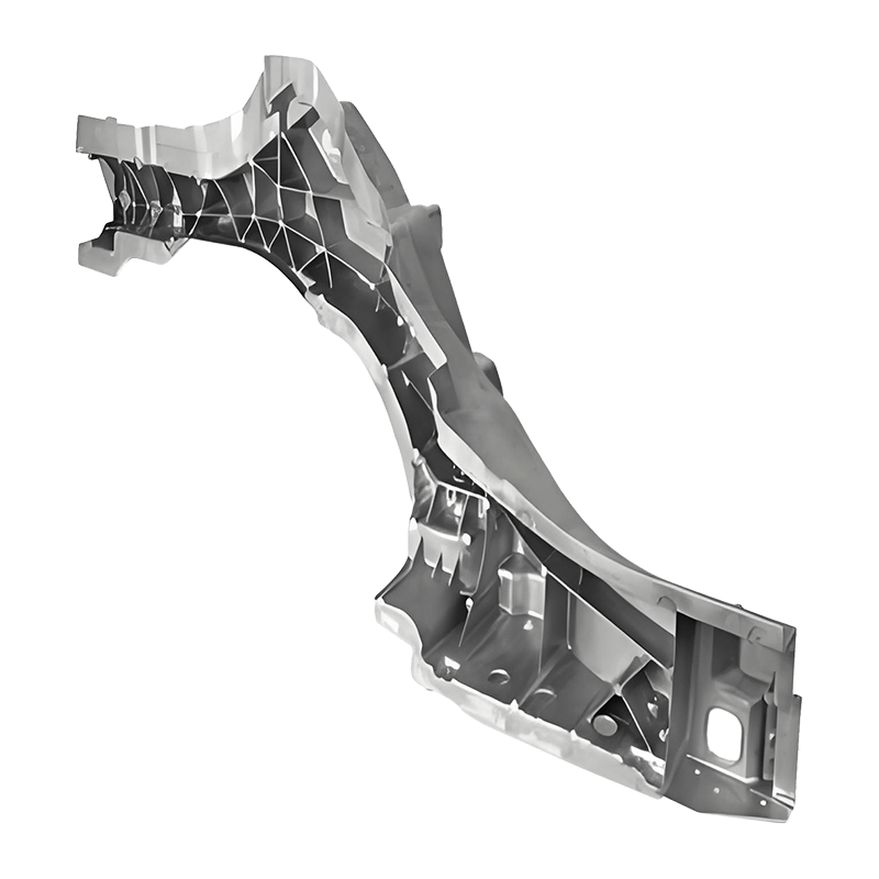
 Die-Cast Automotive Longitudinal Beam for Body StructureAn OEM/ODM die-cast body-skeleton component intended to support the body and absorb collision energy, suited to structural-part programs requiring controlled die design.View Product →
Structural parts are a good example of why process and tool design have to be solved together. A longitudinal beam or a shock tower needs controlled filling, well-placed overflows, uniform die temperature and a ejection plan that does not distort a thin, long section — problems that are solved in the die, not in the quotation.
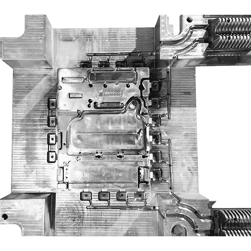
 Die-Casting Mold for Automotive Controller HousingsAn OEM/ODM mold offering for producing automotive controller housings, relevant when evaluating tooling and process fit before committing to die-cast production.View Product →
For programs that sit near the boundary between processes, the honest answer is sometimes that neither supplier should bid. A 40 g stainless steel bracket at 3,000 pieces per year belongs in machining. A 3 kg aluminum housing at 500 pieces per year belongs in sand or gravity casting. Recognizing those cases early saves a tooling investment that would never amortize.
Pulling the comparison back to a single working rule: die casting vs metal injection molding is decided by mass, material and feature scale long before it is decided by tolerance. Aluminum above roughly 100 g with walls of 1 mm or more and volumes in the thousands points to die casting, where cycle time and part size carry the economics. Steel or high-temperature alloys below roughly 150 g with fine features and volumes in the tens of thousands points to MIM, where near-net shaping replaces multiple machining setups. If both routes remain plausible after that filter, the deciding factor is usually the drawing: one process will require a redesign that the other accepts as drawn.
The best next step is not a longer comparison table but a specific one. Take the top three part numbers by annual spend, confirm alloy and volume, and ask for a design-for-manufacture review from each route before any tooling is quoted. The review will surface the thick boss, the missing draft, or the tolerance that forces a machining operation — and those details, not the process brochures, are what determine the final piece price.


Before a part ever reaches production, every buyer eventually asks the same question: should this component be injectio...
READ MOREA 12-week die casting mold build can look competitive on quote and still become the expensive option if the first trial...
READ MOREA mold quote for an aluminum die casting mold can swing by 30–50% for the same nominal part. The difference is rarely t...
READ MOREMaterials & Manufacturing Yes, Aluminum Die Casting Parts are consistently lighter than Cast Iron Parts when engin...
READ MORE

Sun Yuejun: +86-13806631860
Wang Shiyong: +86-15958891460 / 15058297768
Dove Yao: +86-18625086675


Copyright © Ningbo Dinghong Mould Co., Ltd. Rights Reserved. Custom Precision Die Casting Aluminum Alloy Parts Manufacturers
